Presentation
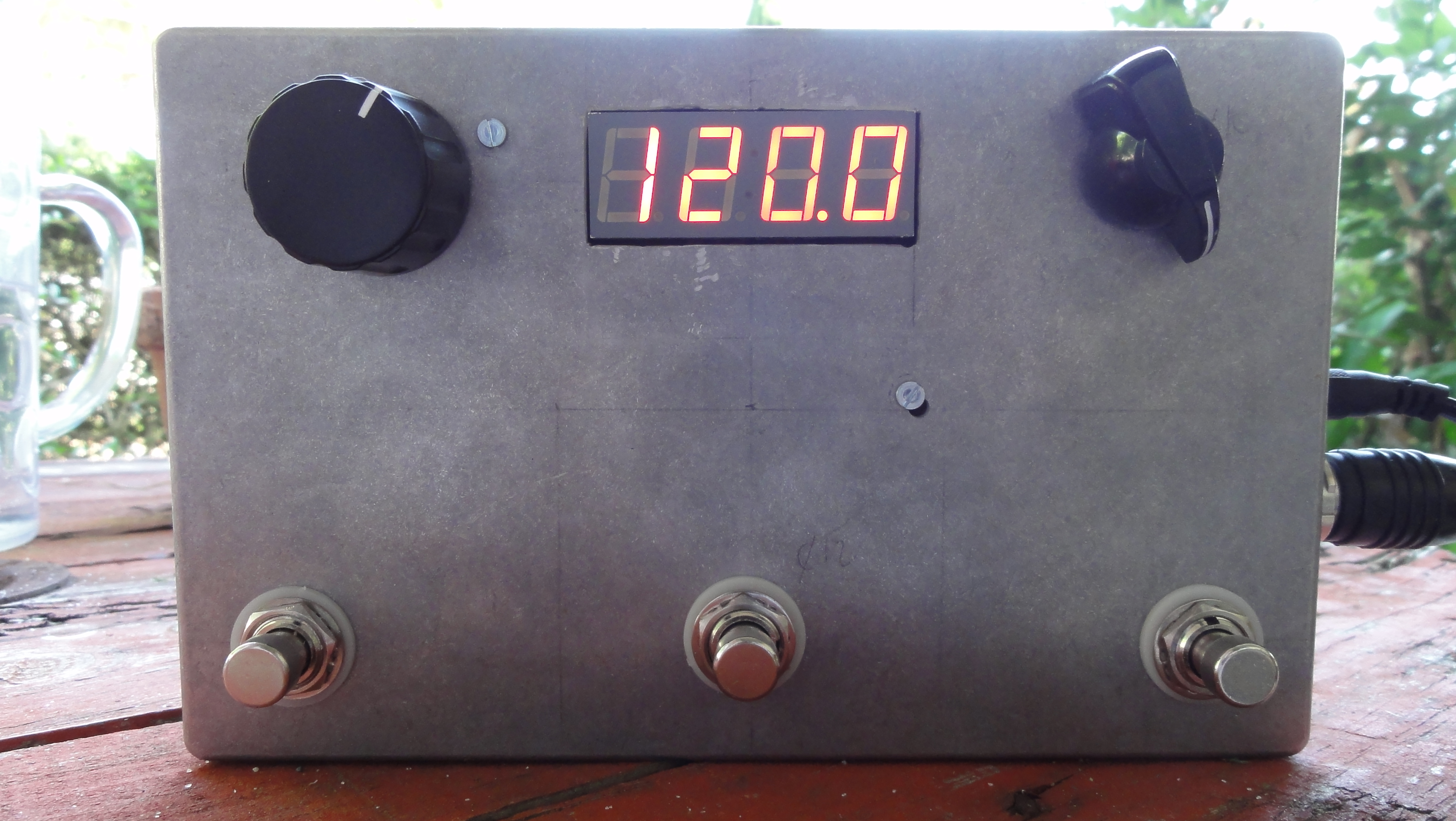
Padchokola is an Arduino based Midi controller which comes with some added synchronization capabilities, since it can be set as Midi Clock master or MTC (Midi Time Code) master. You can do it yourself either from scratch using the plans and informations here, or by buying the kits from me (send me a message if you're interested).
Features
- 3 footswitches, sending different events on short and long hold
- Midi Clock master to control the tempo of your sequencer, looper, drum machine, etc.
- Tap tempo for midi clock mode
- Midi Timecode master to synchronize and control playback on different sources.
- Rotary encoder for tempo setting (in midi clock mode), position in song in seconds (in MTC mode) or midi program change in default CC mode
- 3 positions switch to choose between normal controller (CC) mode, midi clock master or MTC master mode.
- 4 digit display
- Arduino-based design (fully compatible with Arduino IDE given that you have an external programmer)
Licensing
- Since the board design is based on Adafruit's Boarduino, it stays with the Creative Commons 2.5 - Attribution - Share Alike license. So does the 7-segment display extension.
- I wrote all the code from scratch and decided to put it under GPLv2. I started with the Timer1 library to handle interruptions for the midi clock, but it happened to behave strangely at high bpm so I decided to come back to something simpler.
Make it
You can buy the kit from me (mail me).
Parts list for the whole pedal (with sync and display and 3 switches)
- The 2 circuit boards
- 1x rotary switch with 3 positions (for the 3 modes)
- 2x Knobs to cover the switch and encoder
- 1x rotary encoder that you can mount on a panel
- 2x shift registers 74HC595
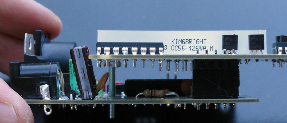
- 1x 7 segment display, 4 digit Kingbright CC56-12EWA (common cathode)
- 2x Transistor BC547A/B/C
- 3x Foot switches SPDT or more complex if you know how to wire them
- 3x Ceramic capacitor 0.1uf, 6.3V
- 2x Ceramic capacitor 22pf, 6.3V
- 1x Electrolytic Capacitor 10µF; voltage 25V
- 1x Electrolytic Capacitor 100µF; voltage 6.3V
- 1x Rectifier Diode 1N4001
- 1x Green LED - 3mm
- 1x Red LED - 3mm
- 1x 2.1mm DC Barrel Jack
- 1x Generic double row male header - 6 pins
- 1x generic single row male header - 5 pins
- 1x generic single row female header - 5 pins
- 1x Atmega328-20PU micro controller
- 1x 28pin socket
- 1x Voltage Regulator 7805CV - 5V TO220
- 1x DIN-5 jack (MIDI). Latest revisions of the board are drilled for a SDS50-J
- 1x 10k Ω Resistor
- 2x 1k Ω Resistor
- 3x 220 Ω Resistor (1 for the main board, 2 to solder on the rotary switch)
- 1x Subminiature switch KRS0611
- 1x 16Mhz Crystal
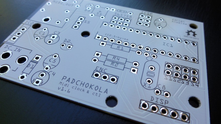
Soldering of the main board
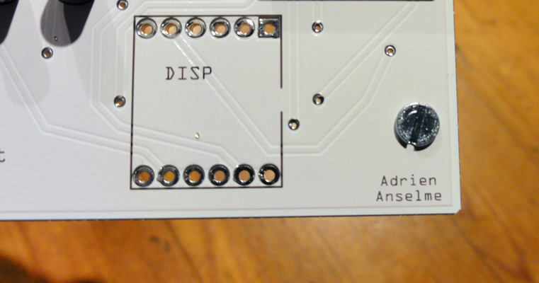
The bare circuit board:
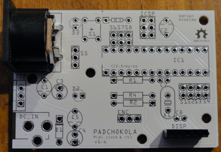
Here I soldered the Midi connector and display female connectors on the bottom right.
Then the first part of the power supply stage: the DC connector, the diode (with the ring mark towards the top), the 100uF electrolytic capacitor at the bottom (minus sign on the bottom), and a 0.1uF ceramic capacitor right above it.
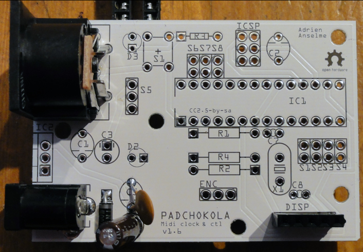
Second part of the power supply, from left to right: 7805CV voltage regulator (with the metal part facing left, so that we can make it touch the aluminium case later for a better heat diffusion), 0.1uF ceramic capacitor, 10uF electrolytic capacitor (minus sign on top), green LED (short leg on the left), 1kOhm resistor. Now if you plug your power supply, you should see the (green) light. If not, check your soldering joints and the voltages with a multimeter.
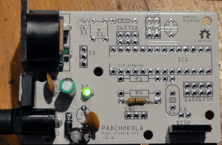
Now the easiest part: solder the other connectors (ICSP and main chip), and the remaining resistors (from top to bottom: R3 = 1kOhm, R1 = 10kOhm and R4 = 220Ohm).
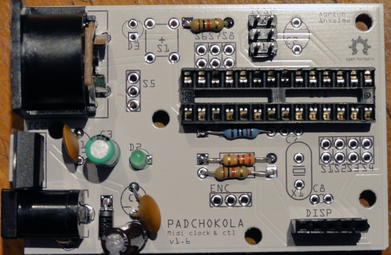
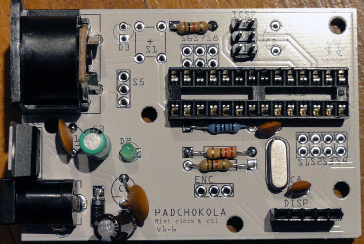
You're almost done now: solder the quartz oscillator and its two 22pF capacitors. All these have no polarity. It's important to solder the chip socket BEFORE the 10kOhm resistor and 22pF capacitors, because they're quite close to each other and it's easier to do it this way.
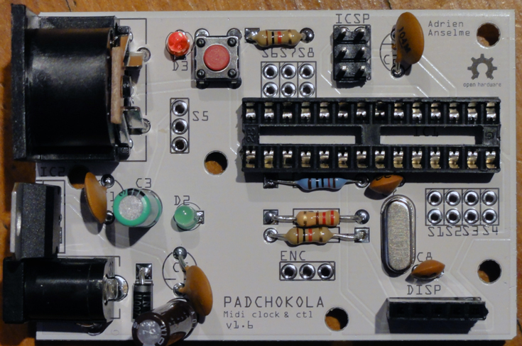
Here is the board, almost complete. I just soldered the red LED (short leg on top), micro switch, and remaining 0.1uF capacitor (C2).
What's left to solder are the wires for the various foot switches (S1 to S4 and S6 to S8), encoder (ENC) and mode switch (S5), that you'll all mount on the panel of your enclosure. So pick an appropriate wire length and start soldering them. You can also fit the micro controller in its socket. Careful with the orientation of the chip: the little mark on the chip should be oriented left, just like the socket, so that pin number 1 is the one at the bottom left corner.
Soldering of the display board
After the main board, the display extension is a piece of cake!
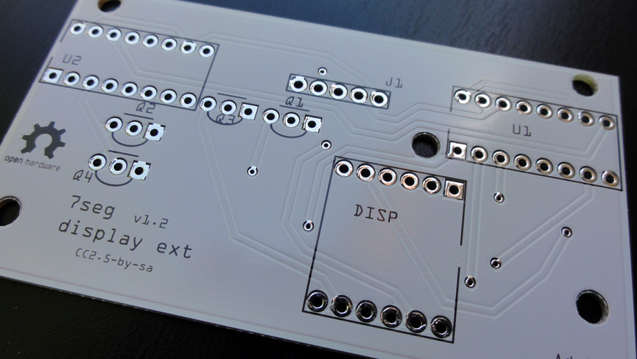
Here is the naked board.
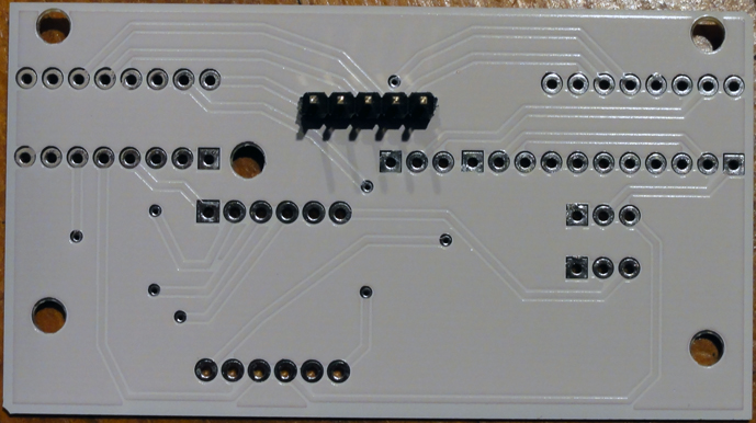
Start by soldering the male header on the other side of the board. This will allow us to connect the circuit to the main board very easily.
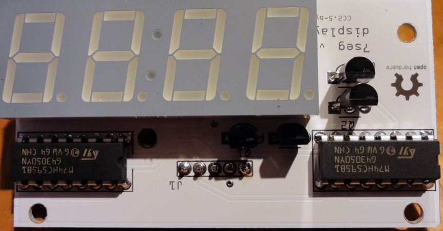
Then the 4 transistors.
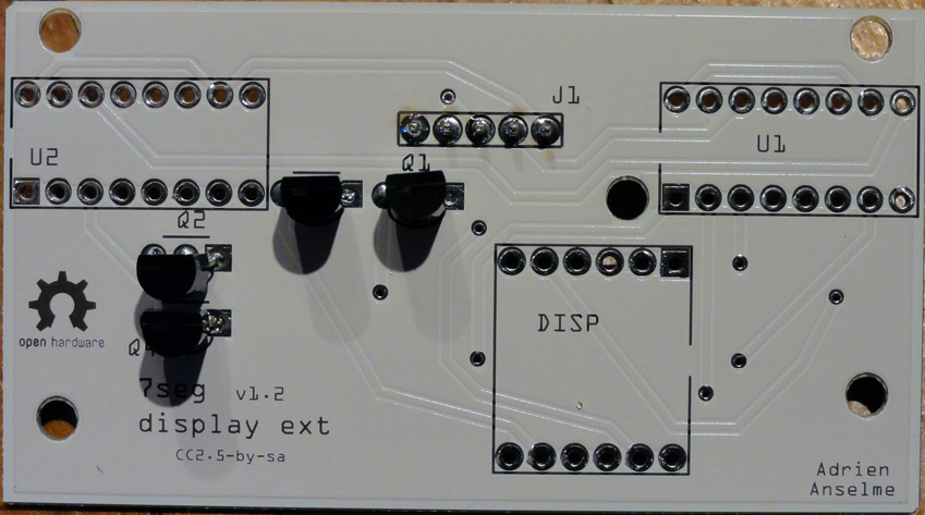
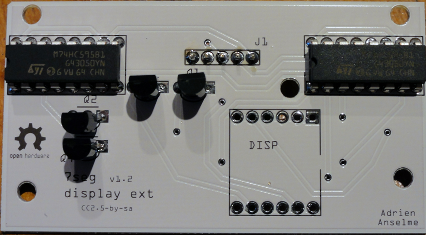
The shift registers, oriented left (look at the half-circle mark).
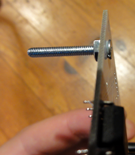
Now the first tricky part: put an M3 screw in the hole at the bottom right corner...
... and tighten a bolt on the other side. We will see why this is needed in the next section.
Now the second tricky part: rotate the board upside down before soldering the display!
Assembly
If you did your homework well, your display board should fit right on top of the main board.
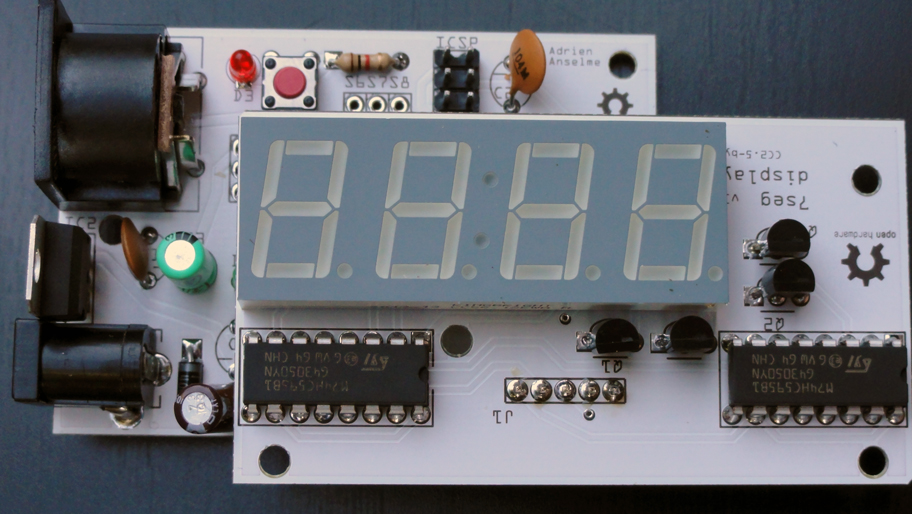
Connect the male and female (DISP) headers on the two boards. The screw we placed earlier aligns itself with a hole in the center of the main board. You can use other bolts here to tighten this up.
Circuit
Circuits were drawn using Fritzing Free software. Check out the files with the extension "fzz" in the repository. You can print the circuit from there.
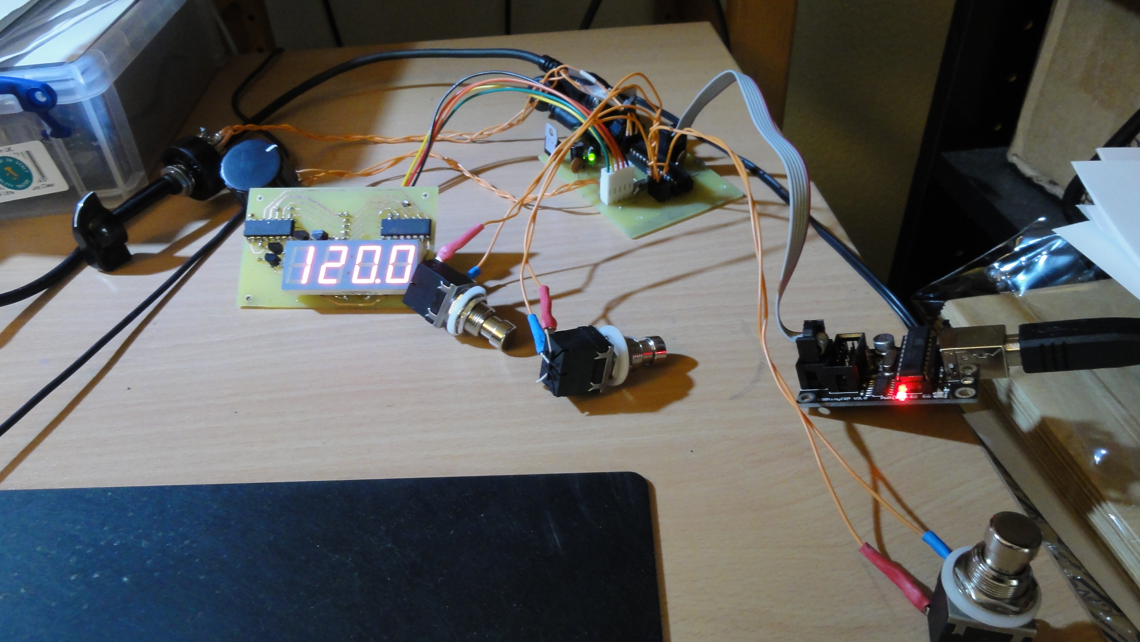
You can also prototype the pedal using an Arduino Uno and do the following circuit:
- Footswitch 1, 2 and 3 to digital pins 5, 6 and 7
- Rotary switch (S5) to analog pin 0
- Midi connector:
- pin 4 to VCC through a 220 Ohm resistor
- pin 5 to TX (also marked Digital pin 0)
- pin 2 to ground
- Rotary encoder pin A to D2, pin B to D3
- 7 seg data pin to arduino pin 4, clock pin to pin 9, latch pin to pin 10.
Code
Download the code from the top of this page (or click here if you're lazy), or from the github page, and open it in the Arduino software. If you etched your own PCB from the provided Fritzing files, you'll need an ISP programmer like USBtinyISP or equivalent to push your code to the controller. Burn a bootloader first using "Tools > Burn bootloader" (don't forget to select the kind of programmer you use in the menu just above) if you're using a fresh microcontroller. Then to upload your code, you need to use "File > Upload Using a Programmer".
Don't hesitate to send pull requests to improve the code (or circuit)!
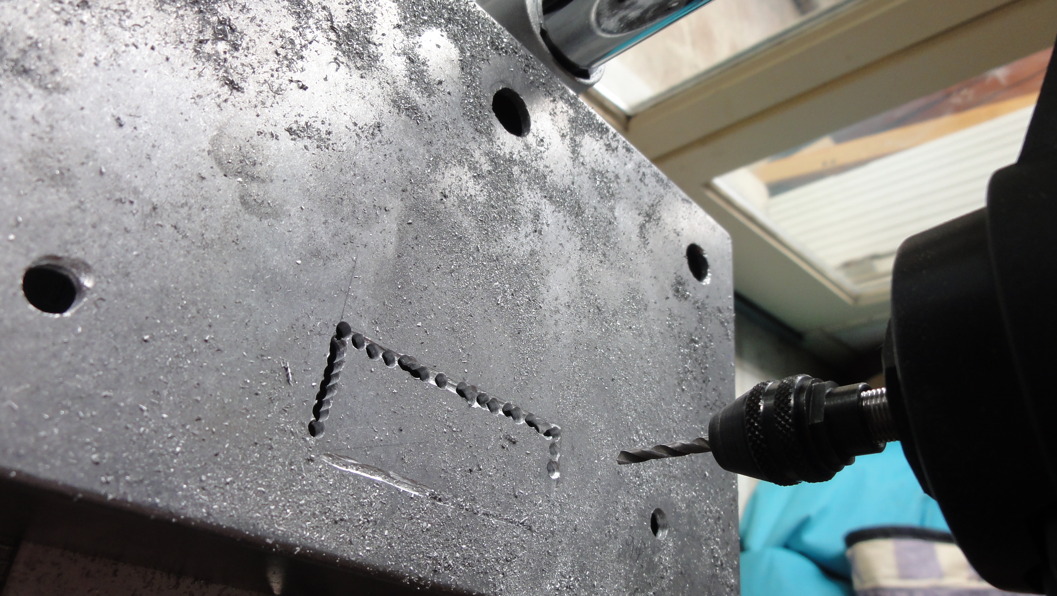
Enclosure
How it works
TODO
FAQ
Where does the name "Padchokola" come from?
It is a very famous (and bad) joke made even more famous with the movie The Intouchables where the disabled guy asks his assistant for candies, and the assistant answers "No you can't. No arms, no chocolate!". No chocolate being "Pas de chocolat" in French, it became funny to use it to describe a pedal you only need your feet to operate... I told you it was bad!
Who are you?
I'm Adrien (@adanselm), a professional developer. I co-founded a company called Springbeats which works on music production software. I happened to need a foot controller to record myself playing the guitar. I also added some midi synchronization capabilities to better test our software. I figured it could be useful to others. I sometimes share my thoughts on entrepreneurship, music and software on twitter or google plus.